1. Información de la pieza de trabajo
Rango de diámetro: 600 mm – 1400 mm
Longitud de pulido efectiva: ≤ 2500 milímetros
Peso de la pieza de trabajo: ≤ 1000 kilogramos
Requisito de molienda: Pulido de superficies de costuras de soldadura circunferenciales, cuerpo de cilindro y tapas de extremo mediante línea de producción
Acabado superficial: ≤ Ra 0,8 μm (no se permiten marcas en espiral)
Tiempo de ciclo: 10 a 13 minutos por pieza (según el tamaño del cilindro para su aceptación)
2. Composición del sistema de molienda y flujo del proceso
Configuración del sistema:
Rectificadora de banda cilíndrica ×1
Cepilladora de cilindros ×1
Máquina pulidora de tapas de extremo CNC ×1
Pasos del proceso:
Rack de carga:
Para colocar cilindros de GNL antes de la molienda (estación única)
Incluye transportador de rodillos elevadores
Posicionamiento manual y preparación de la costura de soldadura
Rectificado de correa de cilindros:
Rectificadora de cinta cilíndrica
Equipado con 2 cabezales de rectificado + 1 mecanismo de desplazamiento
Cepillado de cilindros:
Máquina de cepillado de cilindros (dibujo)
Equipado con 2 cabezales de cepillado + 1 mecanismo de desplazamiento
Utiliza ruedas de trefilado de alambre o no tejidas
Pulido de la tapa del extremo:
Máquina pulidora CNC para tapas de extremos
Equipado con 2 cabezales de rectificado rotativos + 2 mecanismos de desplazamiento
Estante de descarga:
Para la recogida de cilindros terminados (estación única)
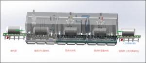
Dimensiones de la línea de pulido (L × An × Al): 17,5 m × 2,5 m × 3,6 m
Proceso de pulido:
- Carga del cilindro (bastidor de carga):
El cilindro se coloca en la plataforma de carga y se selecciona el modo de rodillos. La mesa elevadora de rodillos se eleva y gira el cilindro. En esta etapa, el operador rectifica manualmente la costura de soldadura circunferencial.
Tras finalizar, se activa la función de transferencia de la pieza. La mesa de rodillos desciende y el cilindro se transporta horizontalmente a la línea principal de pulido.
- Rectificadora de banda (rectificadora de banda cilíndrica):
Una vez que el mecanismo de transporte de la rectificadora de banda cilíndrica recibe el cilindro, baja la pieza. El sistema de soporte de rodillos gira el cilindro, mientras dos cabezales de rectificado de banda pulen simultáneamente su superficie.
Después de la molienda, el mecanismo de transporte levanta el cilindro y lo transfiere a la siguiente estación.
- Cepillado/Acabado (Cepilladora Cilíndrica):
El mecanismo de transporte recibe y baja la pieza de trabajo. El cilindro gira nuevamente gracias al sistema de soporte de rodillos, y dos cabezales de cepillado anchos (ruedas de trefilado) lo pulen.
Una vez finalizado el cepillado, el mecanismo de transporte levanta el cilindro y lo transfiere a la siguiente estación.
- Pulido de tapas de extremo (Máquina pulidora de tapas de extremo):
El mecanismo de transporte recibe y baja el cilindro. Este gira gracias al sistema de soporte de rodillos, mientras dos juegos de cabezales de pulido de tres ejes pulen simultáneamente las tapas delantera y trasera del cilindro.
Después del pulido, el mecanismo de transporte levanta y transfiere el cilindro terminado al estante de descarga, completando todo el proceso de pulido.
Nota
Todos los cabezales de rectificado se mueven a lo largo del cilindro, mientras que el cilindro gira horizontalmente a lo largo de su eje.
Los rodillos transportadores utilizados durante todo el proceso (incluidos los estantes de carga y descarga) adoptan un transporte de soporte horizontal** para una transferencia suave.
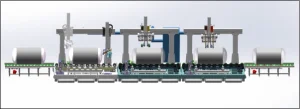
3. Introducción a las máquinas utilizadas para el rectificado.
1、 Máquina pulidora de banda de dos cabezales
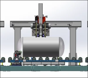
Máquina pulidora de banda de dos cabezales
1.1 Acción de molienda
Según los diferentes tamaños de las piezas, el PLC controla el posicionamiento automático del cabezal de rectificado. Tras entrar la pieza en la pulidora, el transportador interno la posiciona, el motor del rodillo se activa de forma flexible, impulsando la pieza para que gire, el cabezal de rectificado se abre y comienza a rectificar. Ambos cabezales rectifican el cuerpo del cilindro simultáneamente. Tras el rectificado, el cabezal se eleva automáticamente y el motor se apaga. El tope de posicionamiento vuelve a su posición original y el mecanismo de transporte se eleva para transferir la pieza al siguiente proceso de rectificado.
Nota: La molienda y el transporte están controlados automáticamente por PLC.
1.2 Estructura de la máquina
La máquina cubre un área aproximada de 3500 x 2500 x 3600 mm (largo x ancho x alto). La configuración de la estructura se muestra en la tabla a continuación.
|
No. |
Nombre |
Cantidad |
Estructura/forma principal |
Observaciones |
|
1 |
Cubierta protectora |
1 |
|
|
|
2 |
Haz |
1 |
Tubo cuadrado de 200×300×8 mm, soldado y mecanizado. |
|
|
3 |
Columna vertical |
2 |
Tubo cuadrado de 200×300×8 mm, soldado y mecanizado. |
|
|
4 |
Columna pequeña |
1 |
Tubo cuadrado de 150×250×8 mm, soldado y mecanizado. |
|
|
5 |
Placa de montaje |
1 |
Placa T25, mecanizada con acabado |
|
|
6 |
Cabezal de rectificado |
2 |
Cabezal de rectificado de banda de 100 mm de ancho |
|
|
7 |
Mesa de rodillos |
1 |
Mesa de rodillos giratoria (incluye mecanismo de elevación interno) |
Posición del rodillo pasivo ajustable manualmente mediante tornillo de avance; posicionado en la costura de soldadura |
Se mejoran el mecanismo de placa colgante y columna pequeña, utilizando 1 juego de mecanismo de marcha + 2 juegos de cabezales de molienda estándar (como se muestra en la figura)
El ancho de la banda de lijado es de 100 mm y los dos juegos de cabezales de pulido de banda de lijado están instalados con diferentes bandas de lijado para un pulido simultáneo.
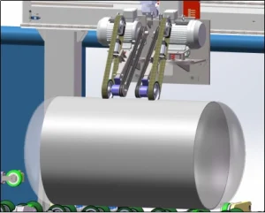
1.3 Información sobre piezas de la máquina
|
No. |
Nombre |
Detalles del componente |
Cantidad |
Observaciones |
|
1 |
Haz |
Conjunto de riel rectangular para viga |
1 |
Xinyidá |
|
Servomotor |
1 |
Inovancia |
||
|
Reductor de RV |
1 |
|
||
|
Engranaje y cremallera |
1 |
|
||
|
Interruptor de viaje |
2 |
|
||
|
2 |
Columna pequeña |
Conjunto de riel rectangular para columna pequeña |
1 |
Xinyidá |
|
Engranaje y cremallera |
1 |
La dureza del engranaje es menor que la longitud de la cremallera |
||
|
Servomotor |
1 |
Inovancia |
||
|
Reductor de RV |
1 |
|
||
|
4 |
Cabezal de rectificado |
Motor asíncrono trifásico de 5,5 kW |
2 |
|
|
Cilindro flotante |
2 |
|
||
|
5 |
Mesa de rodillos |
Motor asíncrono trifásico |
2 |
|
|
Reductor de engranajes |
1 |
|
||
|
Conjunto de transmisión por cadena |
1 |
|
||
|
Juego de tornillos eléctricos para ajuste de distancia de ruedas |
1 |
|
||
|
Juego de ruedas giratorias de apoyo |
1 |
Dos juegos de ruedas giratorias de apoyo |
||
|
Conjunto de riel de ajuste de distancia de rueda |
1 |
La cantidad exacta se determinará más adelante. |
||
|
Mecanismo de elevación |
1 |
Se convierte en rotación de soporte de rodillo después de recibir la pieza de trabajo |
||
|
Dispositivo de transporte interno |
1 |
Transporta la pieza de trabajo a la posición designada |
1.4 Introducción del cabezal de rectificado
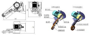
Conjunto de cabezal de rectificado (dos juegos)
Este conjunto de cabezal de rectificado se puede utilizar con diferentes consumibles, como bandas abrasivas, ruedas de láminas, ruedas de alambre, etc. Cuenta con un cilindro flotante en el extremo para proporcionar suficiente presión flotante durante el rectificado. Además, la placa colgante y la columna pequeña permiten ajustar con flexibilidad la posición relativa del cabezal de rectificado y la pieza de trabajo mediante el control del sistema PLC para adaptarse al rectificado de piezas de diferentes especificaciones.
1.5 Componentes de rotación de piezas de trabajo, transporte y parada manual
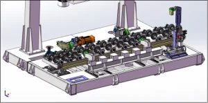
Marco inferior de la pieza de trabajo
- Grupo de rueda motriz giratoria de la pieza de trabajo, 2. Grupo de rueda motriz giratoria de la pieza de trabajo, 3. Conjunto de transporte de la pieza de trabajo, 4. Tope manual de la pieza de trabajo
La distancia central entre los grupos de ruedas motrices y conducidas que giran sobre la pieza de trabajo es ajustable, controlada por servomotor y ajustada eléctricamente para adaptarse al rectificado de piezas de trabajo de diferentes diámetros.
La posición de la rueda motriz giratoria de la pieza de trabajo se ajusta mediante un tornillo manual y se coloca en la soldadura circunferencial para evitar marcas de la rueda en el cilindro.
El conjunto transportador cuenta con elevación neumática, que sube durante el transporte y baja durante el rectificado de la pieza. El grupo de ruedas transportadoras cuenta con un mecanismo limitador de par. Cuando la pieza alcanza la posición especificada y es bloqueada por el tope manual, la rueda transportadora patina y se mantiene en ralentí para evitar impactos en la pieza, lo que podría dañar su superficie.
El conjunto de tope manual está equipado con una función de elevación neumática, que se eleva durante el transporte y desciende durante el rectificado, y la posición de contacto relativa entre la rueda de tope manual y la pieza de trabajo es ajustable para evitar que el codo se suelde en la pieza de trabajo.
1.6. Método de control
Máquina única: pantalla táctil Xinjie + control multieje servo PLC Xinjie, posicionamiento completo de la pieza de trabajo, rotación y rectificado;
En línea: La computadora host PLC del gabinete de control maestro controla la alimentación y descarga, el inicio y la parada del procesamiento de una sola máquina y la recopilación de información;
Forzado: El mecanismo de transporte siempre está levantado, la rueda transportadora gira y se ve obligada a pasar a través del equipo.
2、Máquina trefiladora de alambre de doble cabezal cilíndrico
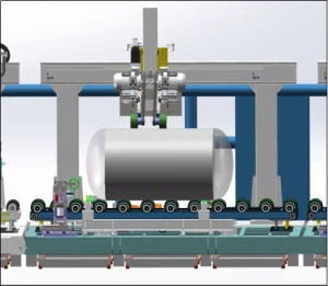
El pórtico, el marco inferior, el mecanismo de transporte, el mecanismo de la mesa rodante, el cuerpo del cabezal de pulido, el método de control, etc. son consistentes con la [máquina pulidora de banda abrasiva de cabezal doble de cilindro].
Se mejoran el mecanismo de la placa colgante y la columna pequeña, utilizando 1 juego de mecanismo de marcha + cabezal de rectificado doble con rueda de trefilado de alambre ancho (como se muestra en la figura)Máquina de trefilado de alambre de cabezal doble de cilindro*1
2.1 Estructura de la máquina
Largo*Ancho*Alto:3500*2500*3600,
|
No. |
Nombre |
Cantidad |
Estructura principal |
Observaciones |
|
1 |
Cubierta de protección |
1 |
|
|
|
2 |
Haz |
1 |
Tubo cuadrado de 200×300×8, soldado y mecanizado |
|
|
3 |
Columna |
2 |
Tubo cuadrado de 200×300×8, soldado y mecanizado |
|
|
4 |
Columna pequeña |
1 |
Tubo cuadrado de 150×250×8, soldado y mecanizado |
|
|
5 |
Plato colgante |
1 |
Placa T25, mecanizada |
|
|
6 |
Cabezal de rectificado |
2 |
Cabezal de rectificado para muela de trefilado de 100 mm de ancho |
|
|
7 |
Mesa de rodillos |
1 |
Mesa de rodillos giratoria (incluye transportador interno “mecanismo de elevación”) |
Ajuste manual del tornillo de avance en la posición de guía, colocado en la costura de soldadura |
2.2 información sobre piezas de la máquina
|
No. |
Nombre |
Información del componente |
Cantidad |
Observaciones |
|
1 |
Haz |
Conjunto de riel rectangular de viga |
1 |
Xinyidá |
|
Servomotor |
1 |
Xinje |
||
|
Reductor de RV |
1 |
|
||
|
Engranaje y cremallera |
1 |
|
||
|
Interruptor de viaje |
2 |
|
||
|
2 |
Columna pequeña |
Conjunto de riel rectangular de columna pequeña |
1 |
Xinyidá |
|
Engranaje y cremallera |
1 |
La dureza del engranaje es menor que la de la cremallera; se indica la longitud de la cremallera |
||
|
Servomotor |
1 |
Xinje |
||
|
Reductor de RV |
1 |
|
||
|
4 |
Cabezal de rectificado |
Motor asíncrono trifásico de 5,5 kW |
2 |
|
|
|
Cilindro flotante |
2 |
|
|
|
5 |
Mesa de rodillos |
Motor asíncrono trifásico |
2 |
|
|
|
|
Reductor de engranajes |
1 |
|
|
|
|
Conjunto de transmisión por cadena |
1 |
|
|
|
|
Conjunto de tornillos eléctricos de ajuste del espaciado entre ruedas |
1 |
|
|
|
|
Grupo de ruedas giratorias de apoyo |
1 |
2 juegos de ruedas giratorias de apoyo |
|
|
|
Conjunto de riel de ajuste del espaciado de las ruedas |
1 |
La cantidad específica se determinará más adelante. |
|
|
|
Mecanismo de elevación |
1 |
Cambia a la rotación del bastidor del rodillo después de recibir la pieza de trabajo. |
|
|
|
Sistema de transporte interno |
1 |
Transfiere la pieza de trabajo a la posición designada |
3、Máquina pulidora de tapas de tanques CNC
El ancho del marco principal y el pórtico se incrementa a 4500 mm, y se utiliza un conjunto de cabezales de pulido de tres ejes para pulir los cabezales en los extremos delantero y trasero.
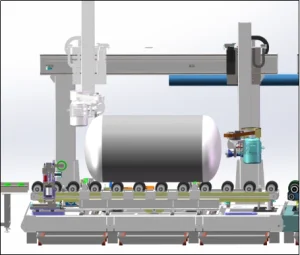
3.1 Estructura de la máquina
|
No. |
Nombre |
Cantidad |
Estructura principal |
Observaciones |
|
1 |
Cubierta de protección |
1 |
|
|
|
2 |
Haz |
1 |
Tubo cuadrado de 200×300×8, soldado y mecanizado |
|
|
3 |
Columna |
2 |
Tubo cuadrado de 200×300×8, soldado y mecanizado |
|
|
4 |
Columna pequeña |
2 |
Tubo cuadrado de 100×200×8, soldado y mecanizado |
|
|
5 |
Plato colgante |
2 |
Placa T25, mecanizada |
|
|
6 |
Cabezal de rectificado |
2 |
Cabezal de rueda de trefilado y correa intercambiable |
Giratorio y reposicionable para adaptarse a la curva de la tapa del extremo. |
|
7 |
Mesa de rodillos |
1 |
Mesa de rodillos giratoria (incluye transportador interno “mecanismo de elevación”) |
Ajuste manual del tornillo en la posición de la polea tensora, colocada en la costura de soldadura |
3.2 información sobre piezas de la máquina
|
No. |
Nombre |
Información del componente |
Cantidad |
Observaciones |
|
1 |
Haz |
Conjunto de riel rectangular de viga |
1 |
Xinyidá |
|
|
|
Servomotor |
2 |
guge |
|
|
|
Reductor de RV |
2 |
|
|
|
|
Engranaje y cremallera |
2 |
|
|
|
|
Interruptor de viaje |
3 |
|
|
2 |
Columna pequeña |
Conjunto de riel rectangular de columna pequeña |
2 |
Xinyidá |
|
|
|
Engranaje y cremallera |
2 |
La dureza del engranaje es menor que la de la cremallera; se indica la longitud de la cremallera |
|
|
|
Servomotor |
2 |
guge |
|
|
|
Reductor de RV |
2 |
|
|
4 |
Cabezal de rectificado |
Motor asíncrono trifásico de 4 kW |
2 |
|
|
|
|
Cilindro flotante |
2 |
|
|
|
|
Juego de poleas |
2 |
|
|
|
|
Servomotor (para rotación del cabezal de rectificado) |
2 |
guge |
|
|
|
Reductor rotatorio |
2 |
|
|
|
|
Conjunto de montaje de consumibles intercambiables |
2 |
|
|
5 |
Mesa de rodillos |
Motor asíncrono trifásico |
1 |
|
|
|
|
Reductor de engranajes |
1 |
|
|
|
|
Conjunto de transmisión por cadena |
1 |
|
|
|
|
Conjunto de tornillos eléctricos de ajuste del espaciado entre ruedas |
1 |
|
|
|
|
Grupo de ruedas giratorias de apoyo |
1 |
2 juegos de ruedas giratorias de apoyo |
|
|
|
Conjunto de riel de ajuste del espaciado de las ruedas |
1 |
La cantidad específica se determinará más adelante. |
|
|
|
|
|
|
|
No. |
Nombre |
Información del componente |
Cantidad |
Observaciones |
3.3 Tanque hIntroducción del cabezal de rectificado Ead
Conjunto de cabezal de pulido de cabezal (dos juegos)
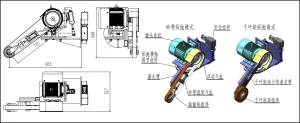
La función principal de este cabezal de rectificado es la misma que la del cabezal de rectificado cilíndrico. La diferencia radica en que este cabezal cuenta con un conjunto adicional de mecanismos de desplazamiento (un conjunto adicional de ejes giratorios en el servocontrol) para facilitar el rectificado del extremo de la pieza. El estado de cada cabezal de rectificado durante el rectificado se muestra en la figura a continuación.
3.4 método de control
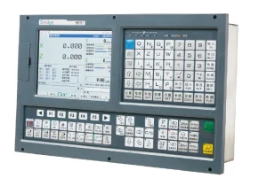
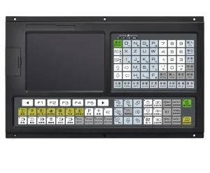
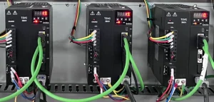
Autónomo: 2 juegos de sistemas CNC de tres ejes GUGE domésticos (viga transversal arriba y abajo, viga transversal izquierda y derecha, control servo del ángulo del cabezal de rectificado), posicionamiento de la pieza de trabajo, rotación, rectificado;
En línea: el gabinete de control maestro PLC controla la computadora host del transporte de entrada y salida, procesamiento de cabezal CNC independiente;
Forzado: El mecanismo de transporte está siempre elevado, la rueda transportadora gira y es forzada a pasar a través del equipo.
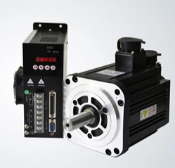
4. Carga y descarga de rack
4.1 Estante de préstamo
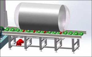
Línea transportadora de rodillos para cilindros de gas + mecanismo de rodillos elevadores
Largo, ancho y alto: 3000*600*700mm
- Seleccione el “modo rodillo”, el rodillo de elevación se levanta, impulsando el cuerpo del tanque para girar (3 rpm) y la soldadura circunferencial se pule manualmente;
- Seleccione “inicio de alimentación”, el rodillo elevador cae y el cuerpo del cilindro se transporta horizontalmente a la línea de pulido.
4.2 Estante de descarga

Línea transportadora de rodillos para cilindros de gas estándar
Largo x Ancho x Alto: 2200 x 600 x 700 mm
5. 3 juegos de carcasas de host (carcasas cerradas con puerto de succión de polvo)
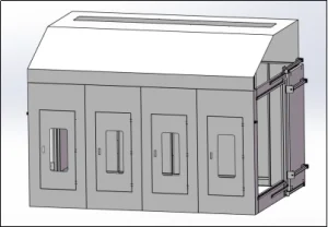
Nota: La carcasa está equipada con un puerto de succión de polvo.
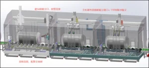
6. Lista de componentes principales
|
No. |
Nombre |
Especificación/Modelo |
Marca |
No. |
|
1 |
Motor del cabezal de rectificado |
|
Wannan |
1 |
|
2 |
Inversor |
|
Zhongchen |
2 |
|
3 |
SOCIEDAD ANÓNIMA |
|
Xinje |
3 |
|
4 |
Reductor |
|
Hongyu |
4 |
|
5 |
Cojinete |
|
Halowa |
5 |
|
6 |
Cilindro |
|
Airtac |
6 |
|
7 |
Cambiar |
|
Schneider |
7 |
|
8 |
Sistema CNC |
|
guge |
8 |
|
9 |
Servomotor |
|
Xinje |
9 |
